New mast cables
Selden manual: 595-557-E 2008-08-13 'Running cables'
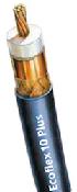
Ecoflex 10plus coaxial
![]()
kjaam cable
s/y MyWay has a mast top antenna with VHF, GSM cellular phone, and FM reception. A filter box for the radios is located down at the instrument panel. We like particularly the mast top GSM antenna as it gives a very good cellular phone coverage in our coastal cruising trips.
In the original old Selden mast, the mast cables exit - in a stupid arrangement - through the heel of the mast, where they are subject to mistreatment and crushing every time the mast is lifted and stepped back, i.e. twice a year. The coaxial cable to the mast top antenna had been sheared during one of these operations and had to be replaced.
Selden has a good down-loadable instruction for the installation of the cables. I followed it more or less to the letter.
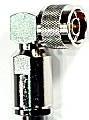
I chose "Ecoflex 10" coaxial cable for the mast top antenna, It is a low loss tinned cable which has good characteristics also for the frequencies of the GSM cellular phone. If you only have vhf radio and AIS, a standard RG218 type tinned coaxial cable would be almost as good. I used 'N' type connectors which are better at GSM frequencies than the often used old "uhf" connectors.
At the same time, I added a 4-pair cable to the other side. I used type "KJAAM 4x(2+1)x0.5", i.e. an industrial instrumentation cable with 4 separate shielded 0.5 sq.mm tinned twisted pairs.. It will have future use for wind instrument, radar transponder, LED tricolor navigation lights etc.
To start the work, I had the mast laying horizontally on 3 supports and peeled carefully away the old coaxial cable. Then I cleaned the old glue residues from the conduit and finally wiped both sides with degreaser and some clean rags.
The mast had a deck sealing made of Sikaflex in the sail groove. It had to be removed, and I had to remove (and later reinstall) the kicker attachment to clean the groove.
I first put into place the coaxial cable: pulled it into place and left some free end for attaching the connectors. Let the cable lay in the place for a day or so that all the kinks have straightened before glueing. If you are not very familiar with installing the coaxial connectors, attach and solder the lower connector before pulling the cable into place.
Then I lifted the cable up from the groove a bit at a time and put a good drop of Cascol glue beneath it into the bottom of the groove, every 20 cm or so, going from the top all the way to the level of the mast collar. As I had half of the glue left in the 300 cc bottle, I then went back and purged again a good drop on top of the cable at the same places; the intention being that the Cascol glue would form a collar around the cable every 20 cm and tie it into the bottom of the groove.
Then the mast was left laying there for the glue to dry for some 2 days or so. Then I turned the mast onto the other cheek and installed the instrument cable the same way as the coaxial.
The mast collar area has to be made a water tight as a deck sealing, so while installing the cables, I lifted each up and purged a healthy dose of Sikaflex at the bottom of the groove, and then pressed the cable into it.. When both cables were installed and Sikaflex dried, I filled the rest of the open space at the mast groove on the mast collar level with Sikaflex and let it dry for a few days.
The cables at the bottom of the mast were terminated to connectors which were installed at the bottom of the sail groove. I opened a 5 cm x 25 cm patch of the groove and installed the connectors at the bottom of the groove where they get some protection when the mast is being handled.
At the top of the mast, the coaxial cable is terminated with an 'N' connector to the mast top antenna, and the connection is protected with self-sealing tape. The instrumentation cable is terminated into a little connection box with screw terminal strips.